Sunday, March 30, 2014

Microchiping - Light Up An LED

Basically there are two ways to drive a LED using a microcontroller:

  • using direct drive (when the current needed by the LED is less then the maximum rated current of the digital I/O pin and the application doesn't need a stable light intensity).
  • using an external driver circuit (like a current source - when you need more precision/constant light intensity).


Direct Drive

In this case you connect the LED directly to the digital I/O pin, together with a current limiting resistor. The value of the resistor can be computed using formula (1), after you know the Vf (forward voltage) and If (forward current) of the LED (this values can be found in the datasheet).

R = (Vdd - Vf) / If     (1)

Our circuits Vdd is 5 V and the LED has a Vf of 3.3 V (typical) at If = 20 mA. The series resistor computed value is 85 Ω.

LED Datasheet Example

In the following schematic LED1 will light-up when the output pin value is '1' and LED2 will light-up when the output pin value is '0'.

Direct Drive Connection

If you want to drive more then a single LED, you will need more current (if you connect the LEDs in parallel) or more voltage (if you connect the LEDs in series). Probably this will exceed the capabilities of the microcontroller, so you'll need to use an external drive circuit (as simple as an transistor).

The code example will blink the two LEDs. Pay attention the way LED2 is light-up (by clearing the value of the associated bit from LATA register).

   void main(void) {

      // internal oscillator configuration
      // use INTOSC with Fosc = 8MHz
      OSCCON = 0x73;

      // ports configuration
      // bits 0 and 1 of port A configured as digital I/O
      ANSELA &= 0xFC;
      // bits 0 and 1 of port A configured as digital outputs
      TRISA &= 0xFC;
      // LEDs off - LATA.B0 = 0, LATA.B1 = 1
      LATA = 0x02;

      // endless loop
      // change the state of the LEDs every 1 second
      while(1) {

         Delay_ms(1000);   // wait 1 s (1000 ms)
         LATA = 0x01;      // turn on LEDs
         Delay_ms(1000);   // wait 1 s (1000 ms)
         LATA = 0x02;      // turn off LEDs

      }

   }

Note: code developed using <MikroC PRO for PIC>. For more information about MikroC IDE go to the dedicated article.


External Driver Circuit

External drivers are used in two scenarios: when you have to switch on more than one LED using a single uC output pin or when you need an exact light intensity.

To drive a group of LEDs using one single digital output you need a semiconductor switch (a transistor) and a power supply. For example if you have n LEDs connected in series the formula (2) for R and the schematic are presented below:

R = (Vext - (n Vf + 0.2)) / If,     (2)

                              n -number of LEDs
                              0.2 - voltage drop on transistor

Driving n LEDs Using One Single Digital Output Pin

Light intensity is directly dependent on the current that flows trough the LED. That makes current sources the best drivers for LEDs.

The next schematic contains a simple current source powering a LED.

Driving LEDs Using A Current Source

One single digital pin required to switch the LED on and off. Value of R is computed with formula (3).

R = 0.6 / If     (3)

Monday, March 24, 2014

Microchiping - I/O Ports

I/O ports are the interface between the uC and the outside world. Every pin of a port can be configured as a digital input/output. Some of them can also be configured as analog inputs.

There are 4 registers used to configure and control I/O ports on PIC16F1938:
  • TRISx Register - Sets up the direction of the port pins;
  • PORTx Register - Used for reading the values of the port pins;
  • LATx Register - Used to set the values of the port pins;
  • ANSELx Register - Sets up the analog/digital function for port pins.
Note: The 'x' from every register name should be replaced with the corresponding letter!


Set up the port direction - TRISx Register

Setting a TRISx bit will make the corresponding pin an input and clearing a bit from the TRISx register will make the corresponding pin an output. To remember it easier I use the following association:
  • 1 - 'i' - input.
  • 0 - 'o' - output.

If you want to set the pins 0, 3 and 4 of the port B (8 bit port) as inputs and the rest of them as outputs you will write the following code line:

   TRISB = 0b00011001;


Reading the port value - PORTx Register

The port pins are set up as inputs. How do you read the value of the port?! You simply read the value of the associated PORTx register.

Let's say the logic levels on pins 2, 3 and 6 are high and the others are low. The value of the port will be 0b01001100 (76 - decimal). The next code lines will run until the value of the port will be greater then 100:

   while(PORTC <= 100) {

      valueSum = PORTC;
      counter++;

   }

You can also read the value of one single pin by using the name of the corresponding bit. For example if you only need to execute some code if the logic level on pin 5 is high:

   if(PORTA.B5 == 1) {

      // code to run

   }


Setting the port value - LATx Register

Your port is set up as output. To set the logic levels on the port bits you only need to write the apropriate value on the associated LATx register.

For example if you need high output levels on pins 7, 6 and 4, value of the LATx register will be 0b11010000 (208 - decimal).

   LATB = 0b11010000;

If you only need to set up the output level of one single pin, use the corresponding bit:

   LATB.B2 = 1;


Enabling/disabling analog function of the port - ANSELx Register

Setting a bit in the ANSELx register will assign the corresponding pin as analog input and will disable the digital input buffer.

Clearing a bit in the ANSELx register will make the corresponding pin function as a digital I/O.

If the pins 0 and 1 need to be configured as analog inputs and the rest of the port as digital I/O, register ANSELx gets the following value:

   ANSELA = 0b00000011;

Microchiping - Internal Oscillator Setup

PIC16F1938 has a configurable internal oscillator module (31 kHz - 32 MHz). Setting it up is a very simple task, involving one single register, except the case you need a 32 MHz Fosc.

PIC16F1938 - Oscilator Module
PIC16F1938 - Oscilator Module (1)

OSCCON register must be altered to setup the internal oscillator.
If SCS<1:0> bits are 10 or 11 the system clock uses the internal oscillator block. Bits IRCF<3:0> are used to select the oscillator frequency.

OSCCON Register
OSCCON Register (1)

For example the function used to initialize the internal oscillator module at a frequency of 16 MHz will look like this:

   void InitIntOsc(void) {
     
      // system clock uses the internal oscillator (SCS<1:0> = 11)
      OSCCON |= 0x03;
      // set the frequency to 16 MHz
      OSCCON |= 0x78;

   }  


(1) PIC16(L)F1938/9 Datasheet - PDF!

Microchiping - Mandatory Circuits

The PIC16F1938 can't be used without the following circuits:
  • stabilized power supply;
  • reset circuit;
  • oscillator;
  • ICSP (in circuit serial programming) connector.


Stabilized Power Supply

Usually the microcontroller circuits draw a limited amount of current from the power supply. That makes the linear regulators like 780x series or LM1117 series the logical choice for powering this applications.

The simplest fixed regulator configuration:

7805 Stabilized Power Supply

To the base configuration you can add protection circuits (overvoltage, reverse polarity) or visual indicators (like a LED). The next image displays the 7805 stabilized power supply with protection circuits and visual indicator.

7805 Stabilized Power Supply With Protection Circuits And Visual Indicator

Diode D1 is used as a reverse polarity protection. It is a Schottky diode with a rated forward current greater then the maximum current generated by the regulator. The forward voltage should be as low as possible to increase the efficiency of the supply.
D2 is a Zener diode used to protect the circuit from overvoltage. The rated voltage of the diode should be less then the maximum input voltage of the regulator circuit.
LED1 indicates that the circuit is powered. R1 resistor is used to limit the current trough the LED.

Note: All the protection circuits are the simplest possible. For more information check out the dedicated article.


Reset Circuit

All microcontrollers (or at least most of them) have a master clear reset pin. Microchip names this pin MCLR and usually uses inverted logic to drive it (to keep the uC in the reset state you should apply a logic '0' to this pin).

The recommended reset circuit is presented in the next picture:

Reset Circuit
Reset Circuit

R3 is a pull-up resistor that powers the pin. It's value is usually 10 kΩ for uC powered with 5V.
R2 protects the pin by limiting the current to a safe value (<25mA).
Capacitor C5 eliminates the transient voltages (voltage spikes). A value of 100 nF is commonly used.

A push-button can be used if you need a external reset. By pressing the button the pin is brought in a low state, resetting the uC.

Reset Circuit With Push-Button For External Reset


Oscillator

Every microcontroller needs an oscillator to generate the device clock, required for the device to execute instructions and for peripherals to function.

Usually you can select a internal or external oscillator. The internal oscillator is cheaper and doesn't consume any space on the board, but it's less accurate and stable then the external ones. 

The most used external oscillator circuit is made out of a quartz crystal and two capacitors:

External Quartz Crystal Oscillator

The two capacitors are used to increase the frequency stability. The values should be between 20 pF and 32 pF, and equal.

Some uC have internal oscillators with frequencies up to 32 MHz. The setup process of a internal oscillator is described into the dedicated article.


ICSP (in circuit serial programming) Connector

The standard connector for Microchip ICSP is the following:

ICSP
ICSP

This interface allows the user to upload the code (.hex file) from the PC to the uC using a programmer device like Pickit, MPLAB ICD or others.

MCLR connects to the uC's reset pin.
Vdd and Vss are are connected to the power and ground pins.
PGD stands for "Programming Data" and must be connected to the corespondent pin on the uC. It can also be named ICSPDAT.
The programming clock (PGC) can also be named ICSPCLK.
The PGD and PGC signals are preferably routed directly to the microcontroller pins, without using other circuit elements.

Tuesday, March 4, 2014

EAGLE CAD - Automatic Rename All The Components Inside A Schematic

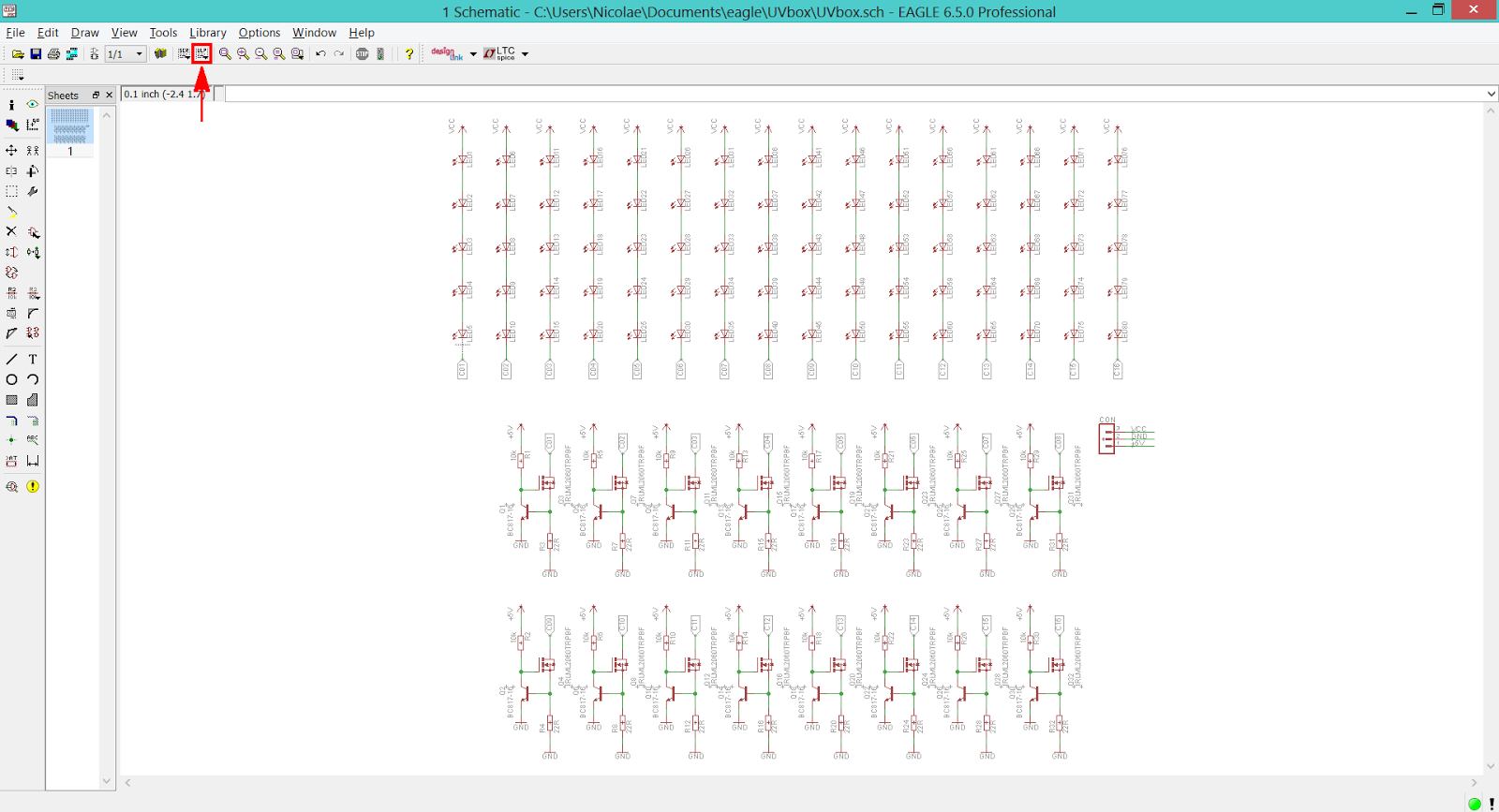
While you're working at a schematic is hard to keep all the component names in order, but at the end it would be nice and helpful if they were. To do this manually it's out of discussion, so we need an automated way to do it. That's why'll be using a User Language Program.

When you're done with you're schematic press the ULP button from the Toolbar and inside the opened window search for the renumber-sheet.ulp file.

EAGLE CAD - ULP Button, Located On The Toolbar

EAGLE CAD - Open The renumber-sheet.ulp Script

You have a couple of options to play with, after what you'll press the OK button to run the script. Simple as that!

EAGLE CAD - Press The OK Button To Run The Script