Sunday, March 2, 2014

EAGLE CAD - Libraries

A library is a file that contains electronic devices. Every device is made out of the symbol (used in the schematic) and the package (used in the board).

EAGLE CAD has libraries for each family of devices like passive components (rcl.lbr), diodes (diode.lbr), transistors (transistor.lbr), power supplies (supply.lbr) and so on.

To use a certain library in a project you should first say tot the program to use that library. This is accomplished in the schematic editor by selecting the Use option from the Library menu. A selection window appear, that allows you to chose the libraries you want to include/use in the project.

EAGLE CAD - How to add a library to the project

EAGLE CAD -The Use Library Window
EAGLE CAD - Use Library Window

Once included, the library can be accessed with the tool Add from the tool panel. Using this tool opens a window that contains all the libraries that are in use.

EAGLE CAD - Add window

If you want to place a resistor on your schematic you should go to the rcl.lbr library and select the appropriate type for your project:

EAGLE CAD - Adding a resistor to the schematic

On the left side of the Add window I selected the rcl.lbr library which expanded. From the expanded list I selected the R-EU option which expanded as well, allowing me to see all available types of resistors.
The left column contains the resistors names and the right column contains the name of the package (footprint). The selected resistor is named R-EU_0207/7 and it's package is a 0207/7 (THT resistor).

The right side of the Add window contains images of the symbol and package, as well as additional data about the selected component.

To use the selected device into schematic simply press the OK button (right side, bottom) and you will be allowed to place the device wherever you want on the workspace by left-clicking. You can place how many components you like, until you press the ESC button.

EAGLE CAD - Adding a resistor to the schematic

Commonly used libraries:
  • Power Supply - supply1.lbr, supply2.lbr
  • Pin Headers - con-lsta.lbr, con-lstb.lbr
  • Screw Connectors - con-ptr500.lbr
  • Resistors (european symbol) - rcl.lbr > R-EU_ (for US symbols replace EU with US)
  • Capacitors (european symbol) - rcl.lbr > C-EU
  • Polarized Capacitors (european symbol) - rcl.lbr > CPOL-EU
  • Inductors (european symbol) - rcl.lbr > L-EU
  • Diodes - diode.lbr
  • NPN Transistors - transistor-npn.lbr
  • PNP Transistors - transistor-pnp.lbr
  • Field Effect Transistor - transistor-fet.lbr
  • LED's - led.lbr > led
  • Voltage Regulators - v-reg.lbr

Free downloadable libraries are to be found on CADSOFT's website.
Another valuable libraries resource can be found on Element14's website (one library for each manufacturer).
To create your own libraries check out this tutorial.

EAGLE CAD - Tools Used In The Schematic Editor

On the right side of the Schematic Editor window you can find a panel full with tools used for create the actual schematic of the circuit. I'm gonna walk you trough the most important elements of this panel, all the other tools being covered in the EAGLE Documentation, available here.

EAGLE CAD - Schematic Editor Tools Panel

move
Move - move the selected schematic element (symbols, wires, junctions) around.

copy
Copy - copy the selected schematic element.

mirror
 Mirror - mirror the selected element on the horizontal axis.

rotate
Rotate - rotate the selected element by 90 degree counterclockwise.

group
Group - groups two or more elements of the schematic. Allows the other tools to operate on more than one element of the schematic at a time.
paste
Paste - used to paste elements from the clipboard buffer.

delete
Delete - delete the selected element.

add
Add - add a new element to the schematic.

replace
Replace - replace the selected element with another type.

name
Name - name or rename the selected element.

value
Value - change the value of the selected element.

wire
Wire - creates a connection between two or more pins.

junction
Junction - shows a physical connection between two or more overlapping wires.

EAGLE CAD - Create A New Schematic

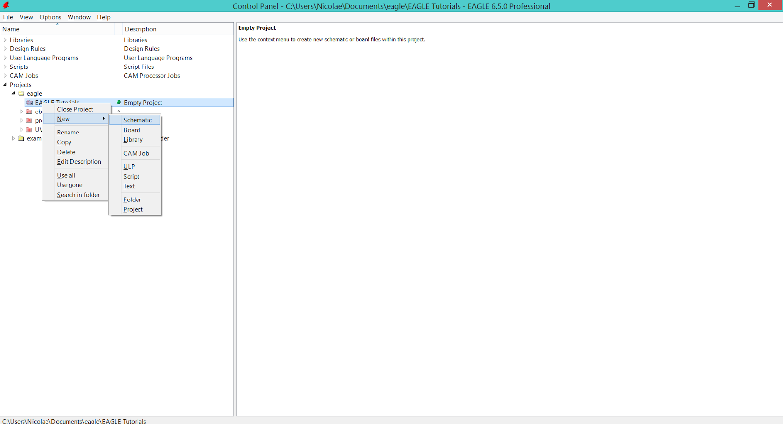
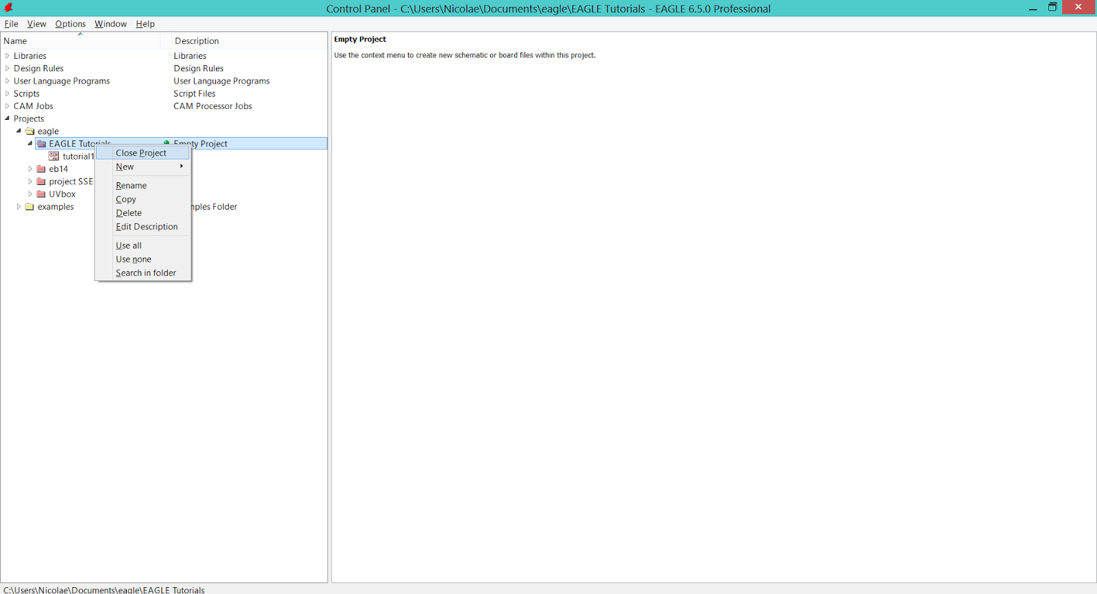
The simplest way to create a new schematic file under the project you're working with is by right-clicking the project name and following the New > Schematic path. This will only work if the project is opened (it has a green dot after it's name in the Control Panel window).

EAGLE CAD - Create a new schematic

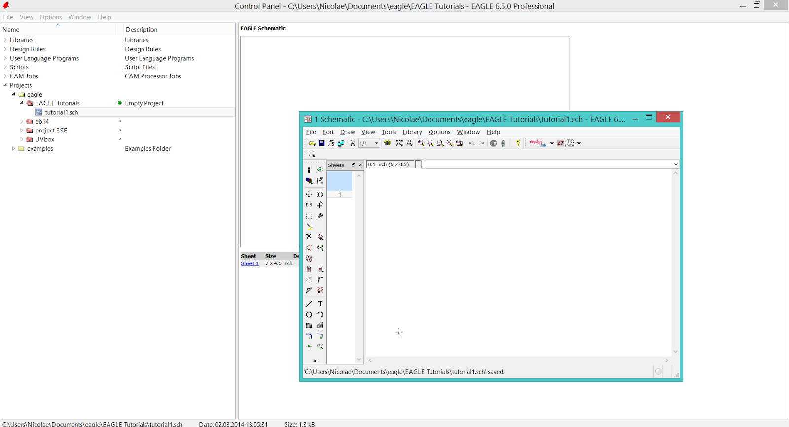
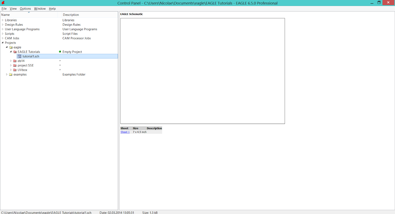
The Schematic window will appear, but the new schematic (.sch) file will be listed under the project only after you'll save it.

On the right side of the Control Panel window you can see a preview of the schematic (empty at this moment because no schematic it's drawn yet).

EAGLE CAD - Schematic window


EAGLE CAD - New schematic listing, under the active project

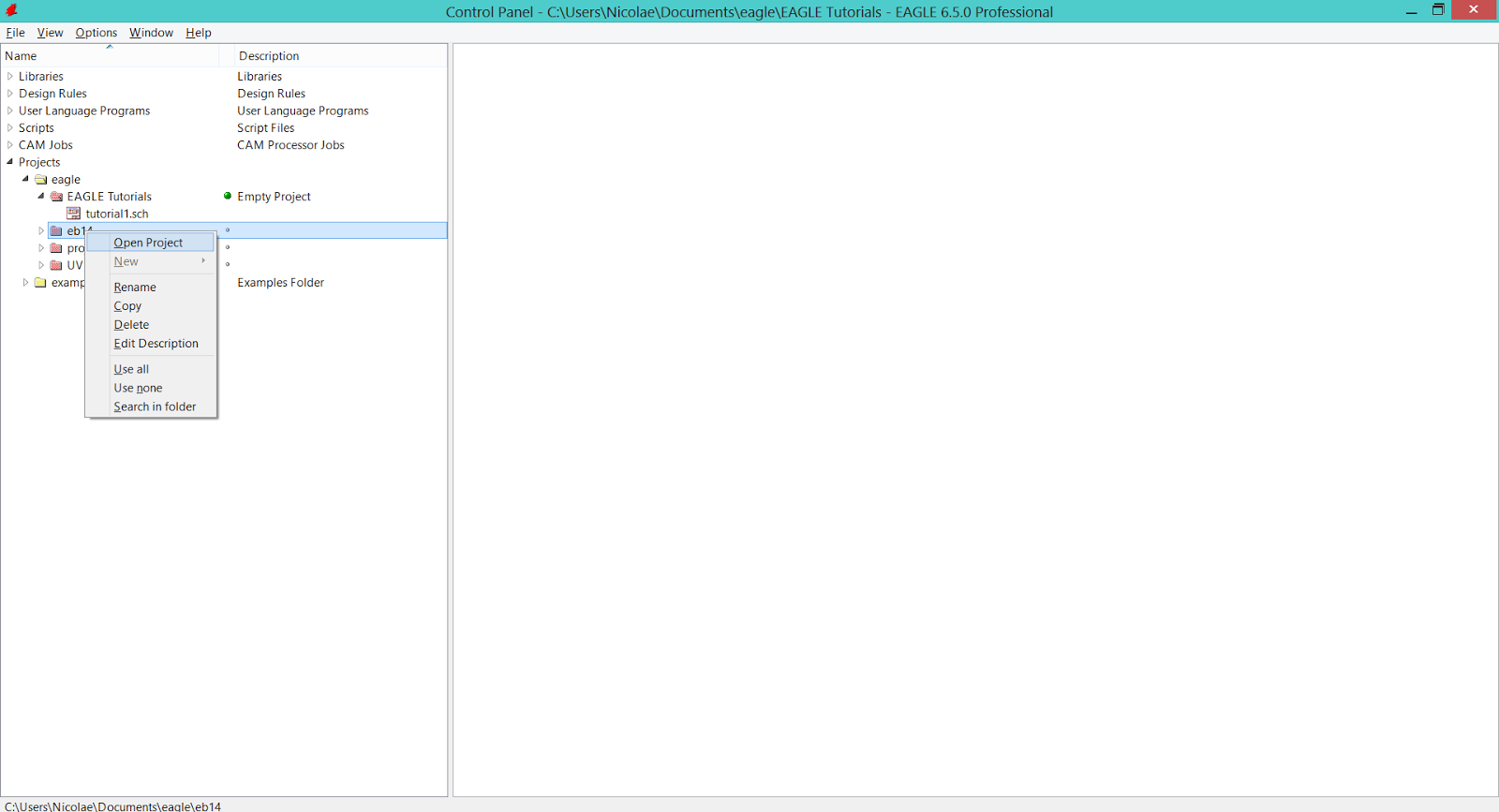
To open/close a project, simply right-click on it's name and chose the Open Project/Close Project option.

EAGLE CAD - How to open a project

EAGLE CAD - How to close a project

EAGLE CAD - Create A New Project

To start a new project in EAGLE CAD you have two options:

     1. Follow the path File > New > Project in the Control Panel window.

EAGLE CAD - How to create a new project v.01

     2. Open the Projects option on the left side of the Control Panel window, right-click on the Eagle folder and chose the New Project option.

EAGLE CAD - How to create a new project v.02

The new project will be placed in the Eagle folder (Control Panel window - left side > Projects option) and you'll be able to give it a name right away.

EAGLE CAD - Name the new project


EAGLE CAD - The Beginnings

One of the most used and simple PCB prototyping software - that's what EAGLE CAD is.

The EAGLE Light Edition can be used for free. The following limitations apply to it:

  • the schematic editor can only create on sheet.
  • the usable board area is limited to 100 x 80 mm (4 x 3.2 inches).
  • only two signal layers can be used (top and bottom).

Loading and printing designs that exceed this limits is allowed.
You can download the latest version of it from here.

EAGLE CAD consists of three building blocks: Control Panel (1), Schematic Editor (2) and Board Editor (3).


Control Panel (1)

Control Panel is the place where you can change the settings of the program, view and edit libraries, design rules, ULP's (user language programs), scripts, CAM jobs and projects (schematics and boards/layouts).

EAGLE CAD - Control Panel


Schematic Editor (2)

This block is used to create the schematic of your circuit. The schematic is a graphical representation of the circuit and it contains all the components and connections between them. Based on this you will build the physical circuit board.

EAGLE CAD - Schematic Editor


Board Editor (3)

Here is the place where magic happens - a new circuit board is born. Based on the schematic you will place the components (represented by footprints) and you will create the physical connections between them (circuit traces).

EAGLE CAD - Board Editor