Just to make use of and to accommodate with the Schematic Editor we'll be sketching a simple circuit. This circuit is used to power a LED with constant current.
What do we need:
- 1 x LED (THT, 5mm type).
- 2 x resistors (SMD 1206).
- 1 x N channel MOSFET (IRF510, TO220 package).
- 1 x NPN transistor (BC847, SOT23 SMT package).
- 1 x push-button switch (Omron 10-xx type).
Let's open the previewesly created schematic file and start adding the components by selecting the Add Tool from the Tool Panel. This action will open the Add window.
Scroll down to the LED.lbr library, expand it and in the LED option you will find the LED5mm - the device that we need, and place it on the workspace.
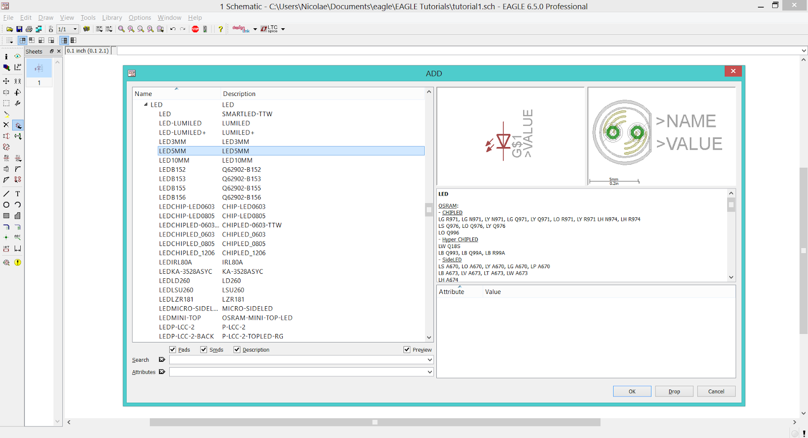 |
| EAGLE CAD - LED Library |
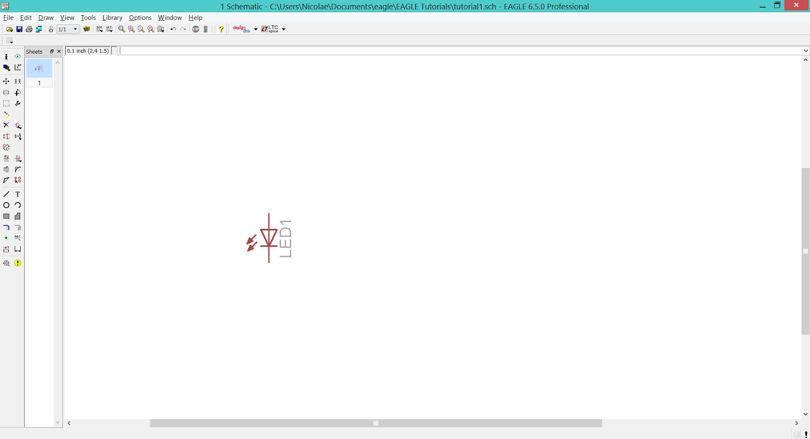 |
| EAGLE CAD - Placing The LED |
Return to the Add window and follow the next path: rcl.lbr > R-EU_ > R-EU_R1206. This is the R1206 SMD resistor that we need. Place two of them on the workspace and return to the Add window.
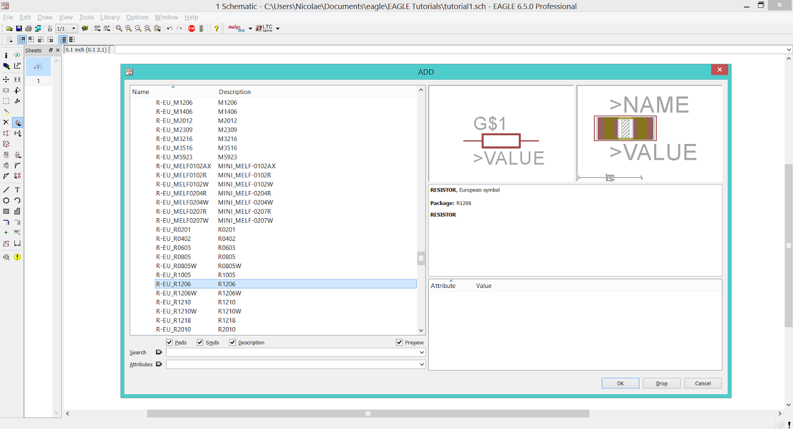 |
| EAGLE CAD - RCL Library |
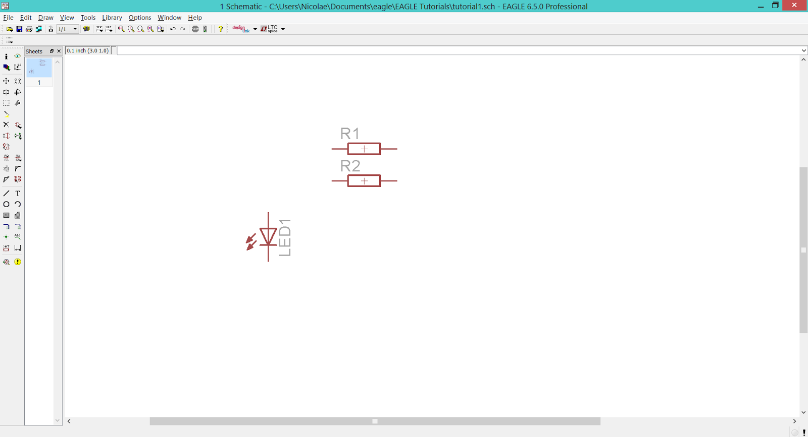 |
| EAGLE CAD - Placing The Resistors |
To add the N channel MOSFET go to transistor-fet.lbr > IRF510. Add one on the workspace.
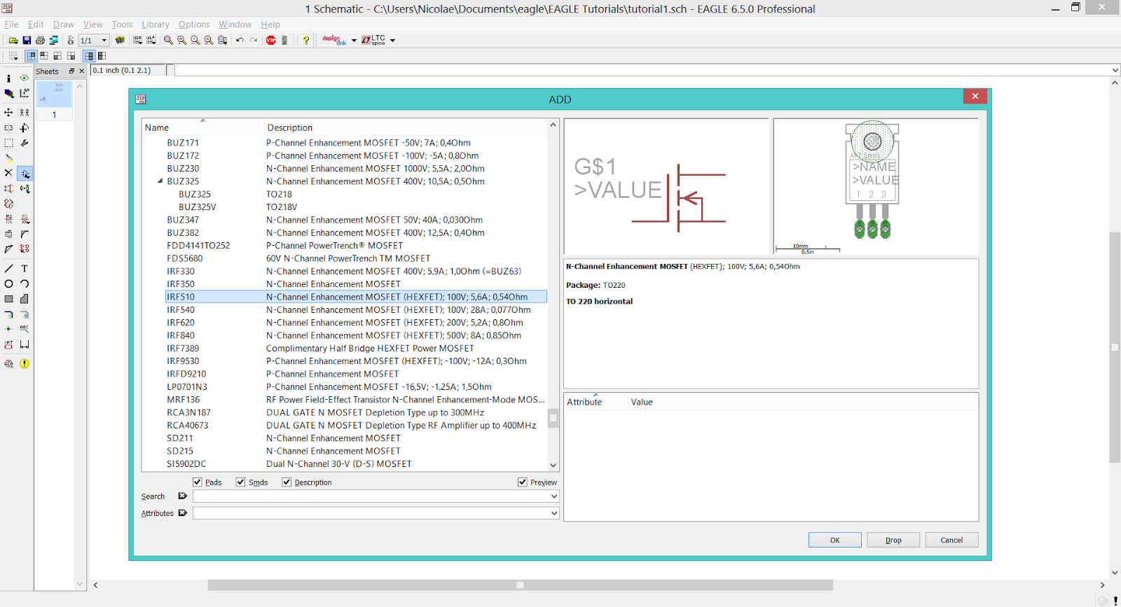 |
| EAGLE CAD - Transistor-FET Library |
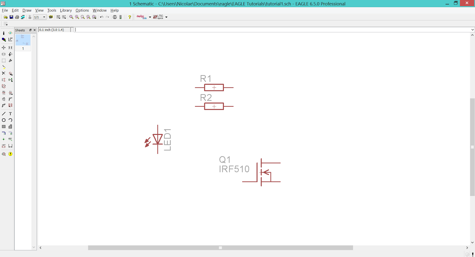 |
| EAGLE CAD - Placing The N-MOS Transistor |
The NPN transistor is to be found in transistor-npn.lbr > BC847* > BC847SMD. Add one on the workspace.
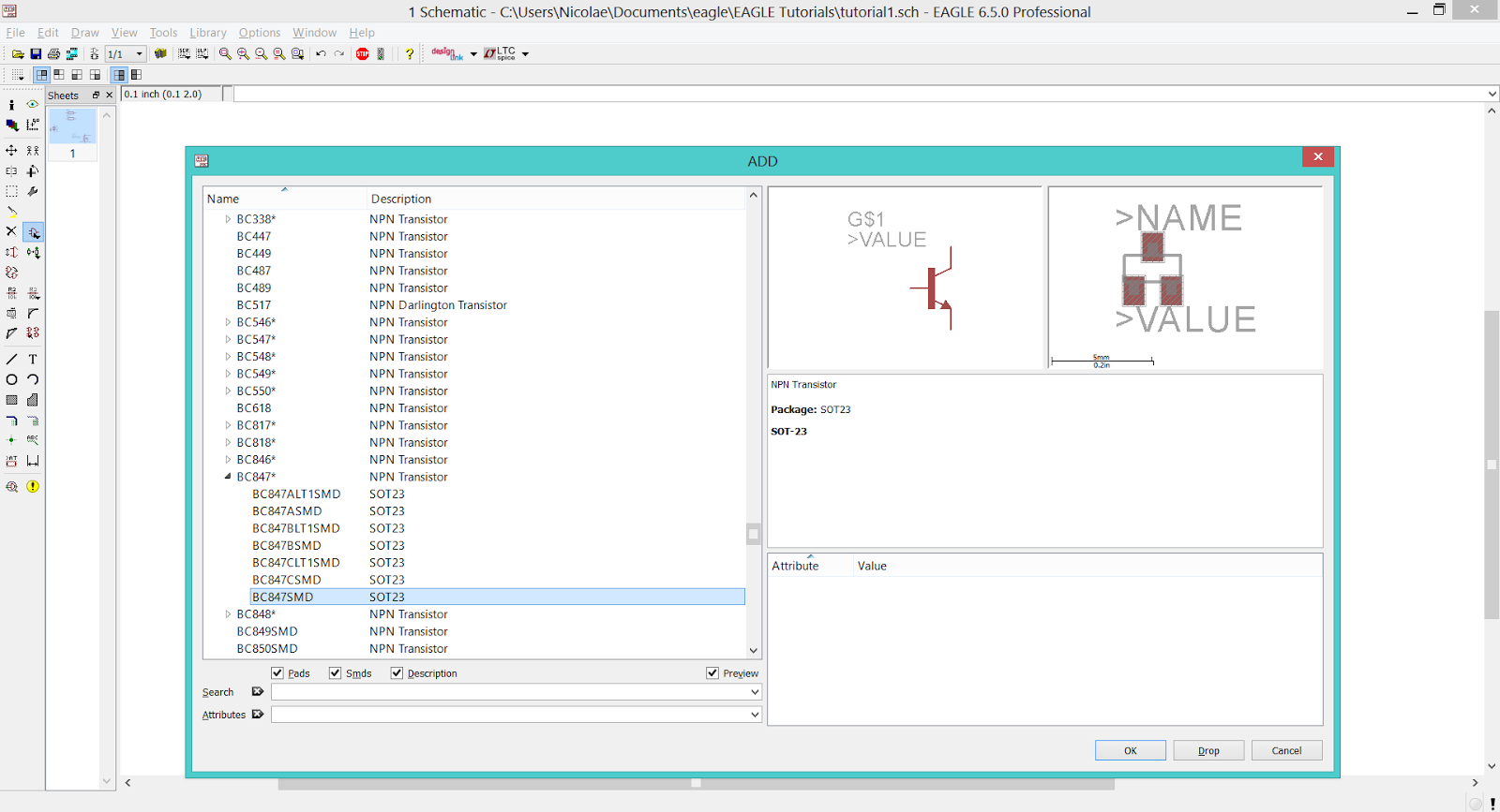 |
| EAGLE CAD - Transistor-NPN Library |
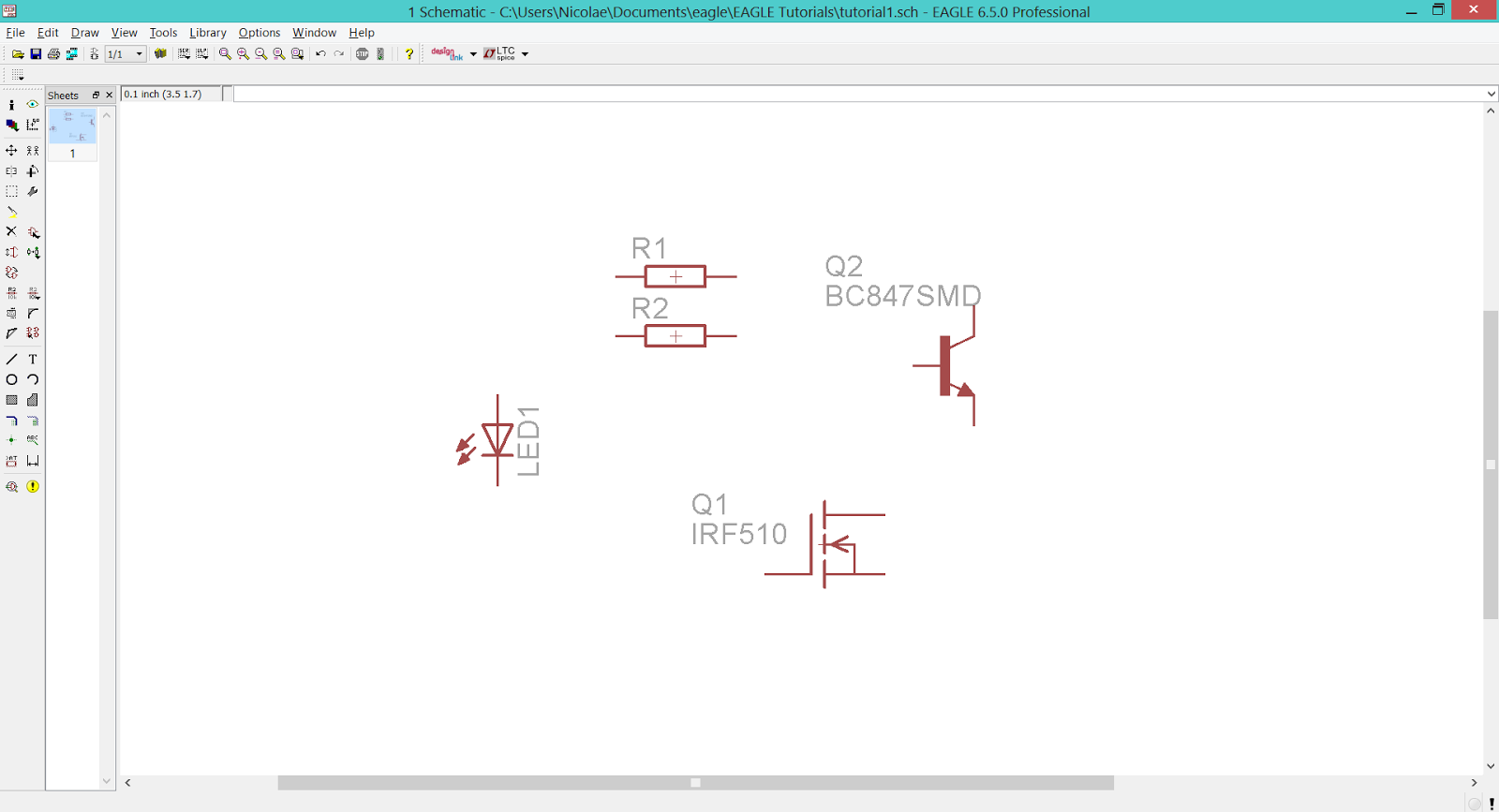 |
| EAGLE CAD - Placing The NPN Transistor |
Add the push-button from switch-omron.lbr > 10-XX.
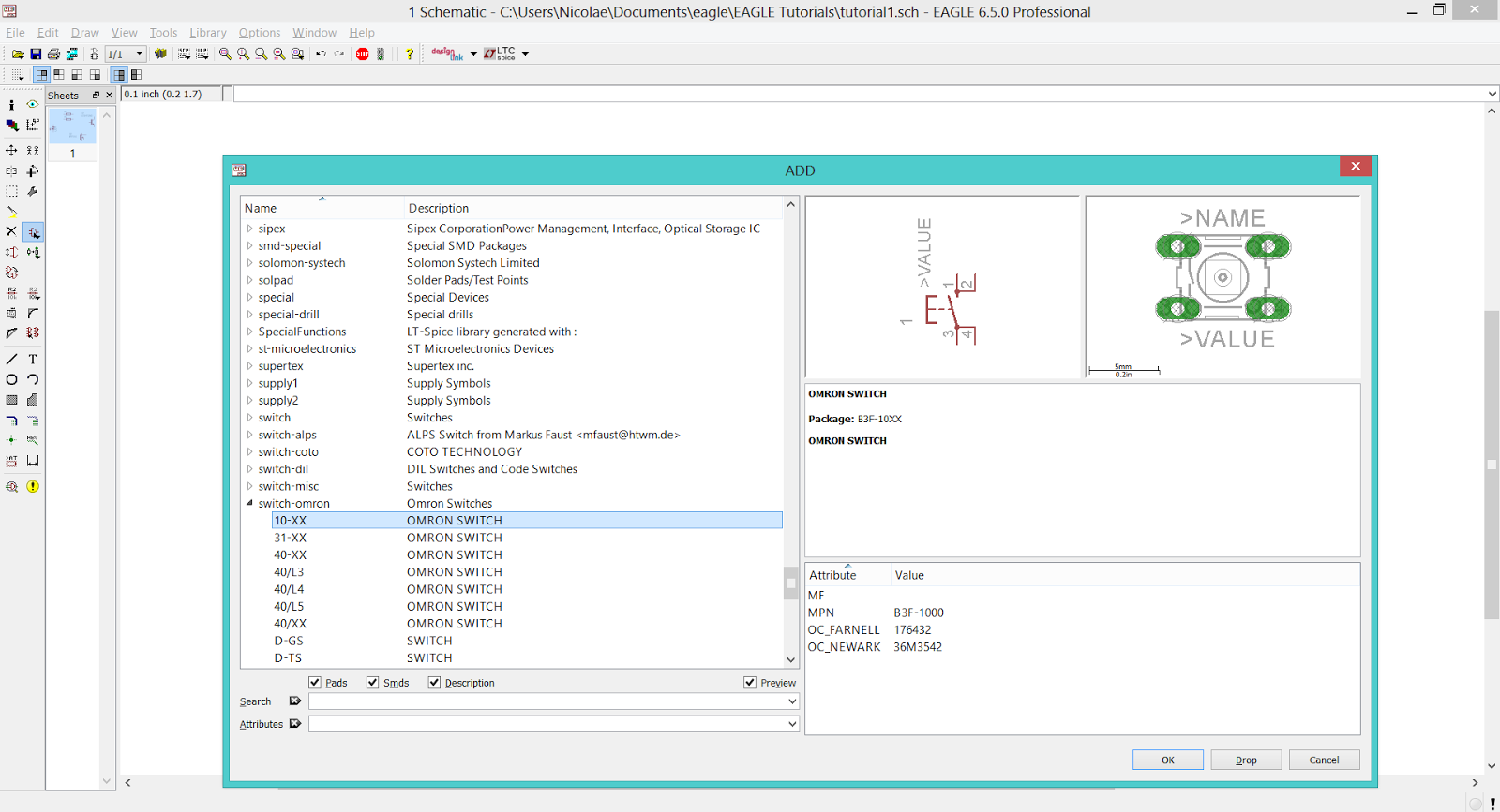 |
| EAGLE CAD - Switch-Omron Library |
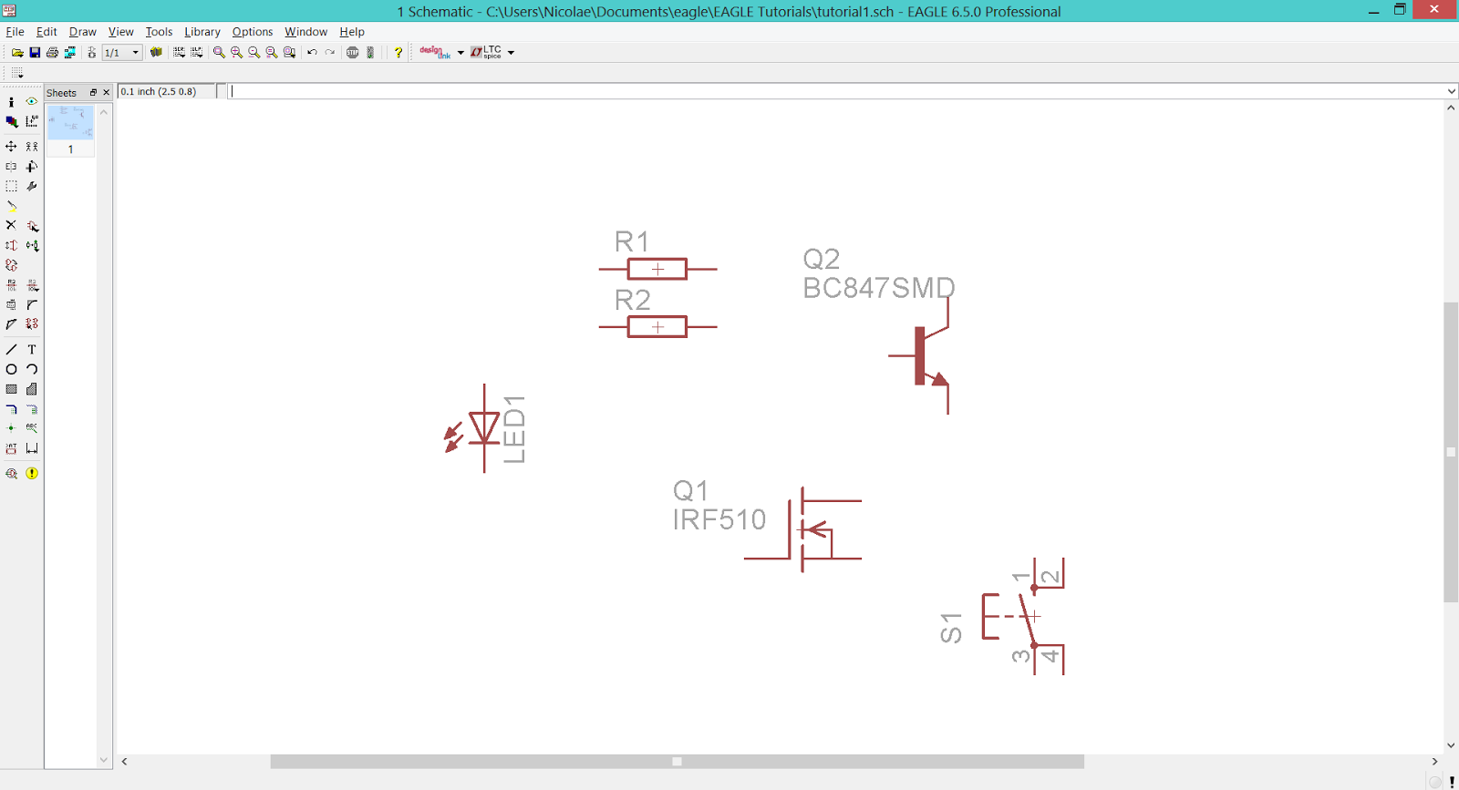 |
| EAGLE CAD - Placing The Push-Button |
Finally, add the power rails from supply1.lbr > +5V and supply1.lbr > GND.
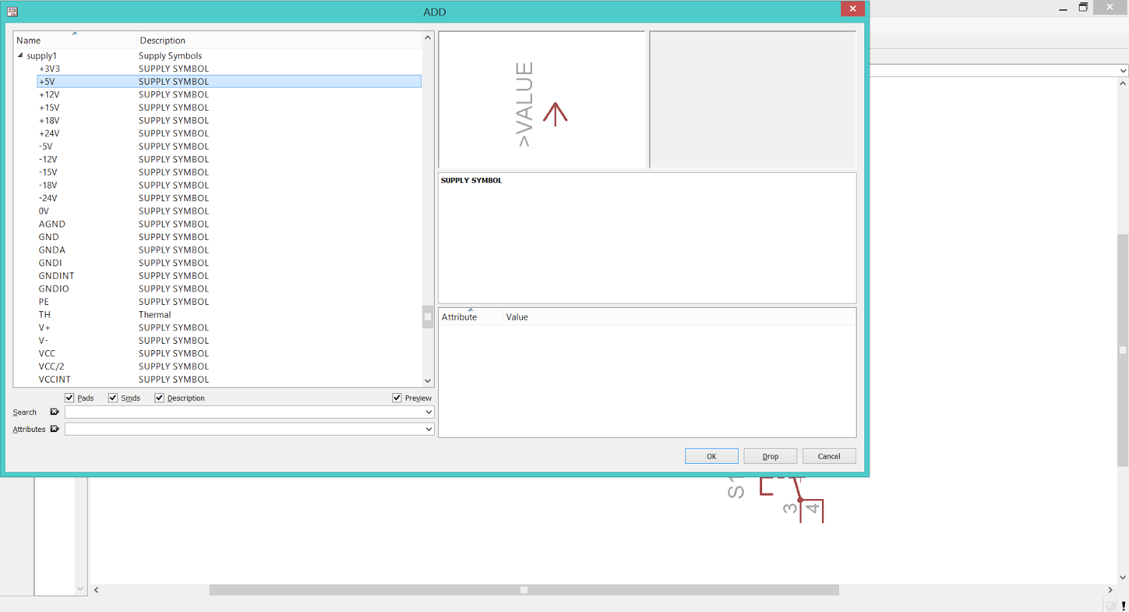 |
| EAGLE CAD - Supply1 Library (+5V) |
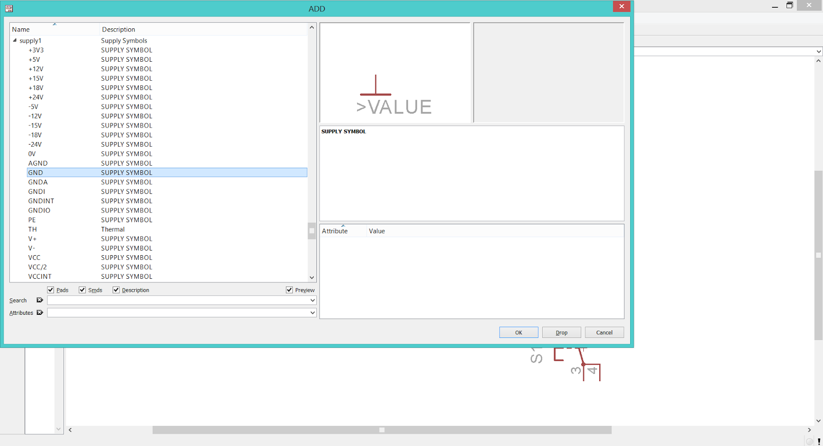 |
| EAGLE CAD - Supply1 Library (GND) |
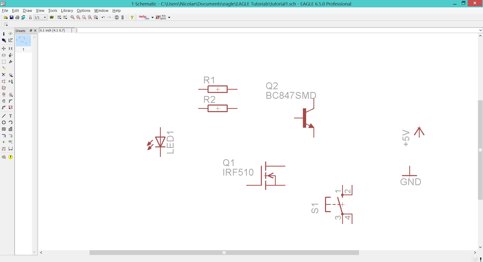 |
| EAGLE CAD - Placing The Power Symbols |
Now we have all the needed components on the workspace, so we can put them in the right order and connect them with the Wire Tool.
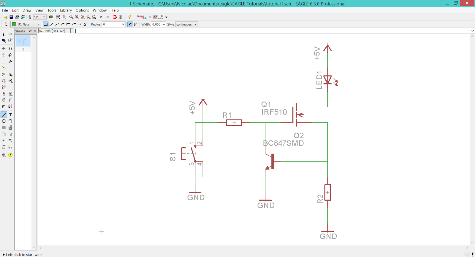 |
| EAGLE CAD - Using The Wire Tool To Connect The Devices Together |
Don't forget to place junctions (using Junction Tool) and give values to the devices (using Value Tool).
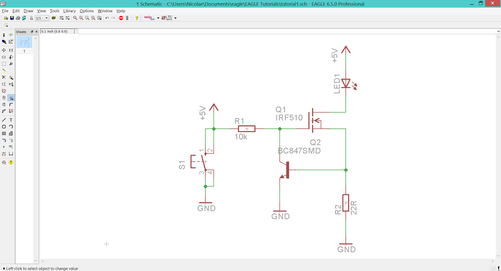 |
| EAGLE CAD - Place Junctions And Give Values To The Devices |
We're ready! The first schematic is up on her way to become a PCB. For a more 'easy to understand' version of this guide, check the following video (coming soon).


No comments:
Post a Comment