Monday, March 3, 2014

EAGLE CAD - Create A Custom Library

To create a new library go to the Control Panel window and follow this path: File > New > Library.

EAGLE CAD - Create A New Library

EAGLE CAD - New Library Window

If everything is OK the Library window will appear. Personally I recommend to save the custom libraries under the same folder with your personal Eagle projects (on a Windows machine the default folder is c:\...\MyDocuments\Eagle). Simply create a Libraries folder where you can save all your custom work.

You can use this custom library in you project by following the instructions in this tutorial.

Information about how to create a custom device can be found here.

Sunday, March 2, 2014

EAGLE CAD - Completing The Board

At this moment we have only a board file with all the devices footprints and highlighted connections inside. To finish the board we have to put every footprint in a position we find useful and replace the airwires with actual traces.

Before we start keep in mind one thing: the traces can be routed (with Route Tool) on both layers of the board: top (red) or bottom (blue).

So... using the Move Tool we place every device in the right place:

EAGLE CAD - Arrange Every Component On The Board In The Right Place

Then we use the Route Tool to create the actual traces, connecting the terminals/pins highlighted by airwires.

EAGLE CAD - Board With Routed Signals

EAGLE CAD - Tools Used In The Board Editor

Beside the tools that we have in the Schematic Editor, Board Editor comes with a couple of his own:

Route - used to create a signal trace between two or more terminals/pins.

Ripup - deletes the traces between terminals/pins.

Polygon - used to create signal planes.

Via - useful for jumping with a trace from a layer to another.

Hole - used for making holes in the board.

EAGLE CAD - Create A New Board

After you're done with the schematic of your circuit simply jump to the next step - creating the board.

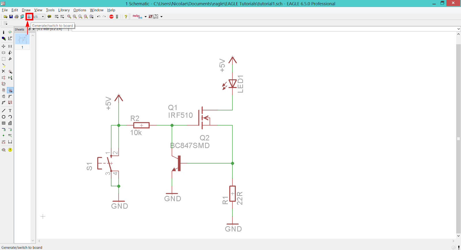
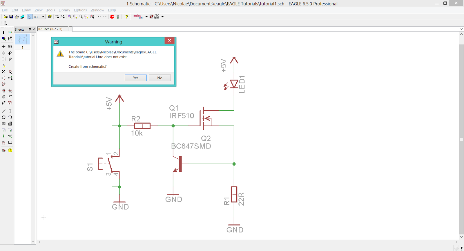
The easiest way to create the board is by pressing the Generate/switch to board button, located on the upper toolbar of the Schematic Editor.

EAGLE CAD - Create a Board File from existing Schematic File
EAGLE CAD - Create a Board File from existing Schematic File 

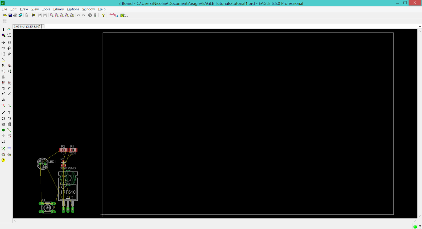
A warning message tells you that the board associated with this schematic doesn't exist and asks for permission to create it. After you click on the Yes button a new Board window opens. This board contains the footprints of all devices included in the schematic file and highlights (using thin yellow lines named airwires) the connections that have to be routed.

EAGLE CAD - Warning Message On Creating A New Board

EAGLE CAD - New Board File Based On A Existing Schematic File

EAGLE CAD - Let's Make A Real Schematic

Just to make use of and to accommodate with the Schematic Editor we'll be sketching a simple circuit. This circuit is used to power a LED with constant current.

What do we need:

  • 1 x LED (THT, 5mm type).
  • 2 x resistors (SMD 1206).
  • 1 x N channel MOSFET (IRF510, TO220 package).
  • 1 x NPN transistor (BC847, SOT23 SMT package).
  • 1 x push-button switch (Omron 10-xx type).

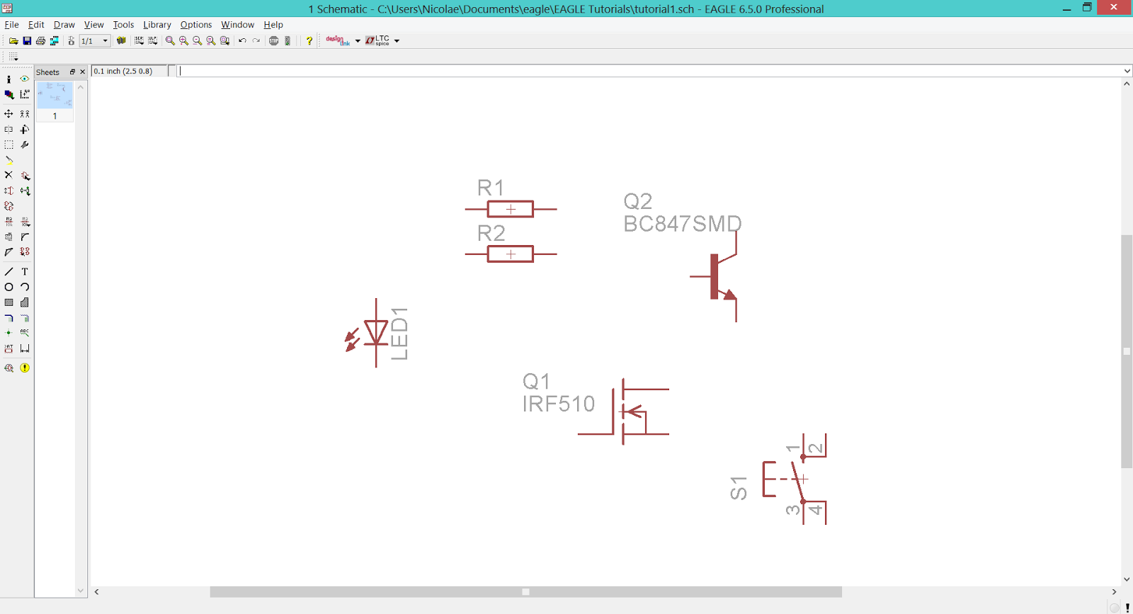
Let's open the previewesly created schematic file and start adding the components by selecting the Add Tool from the Tool Panel. This action will open the Add window.

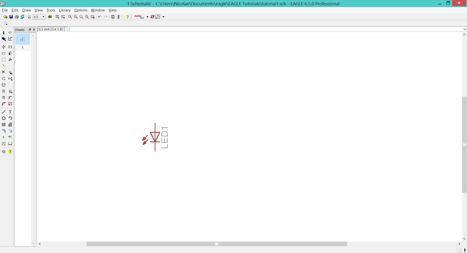
Scroll down to the LED.lbr library, expand it and in the LED option you will find the LED5mm - the device that we need, and place it on the workspace.
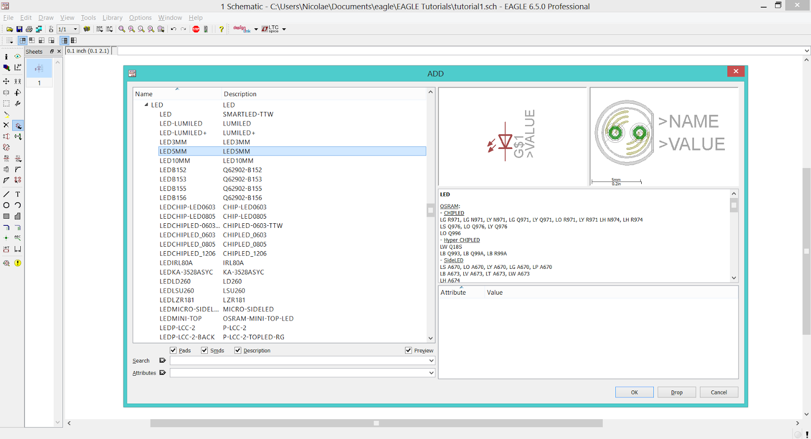
EAGLE CAD - LED Library

EAGLE CAD - Placing The LED

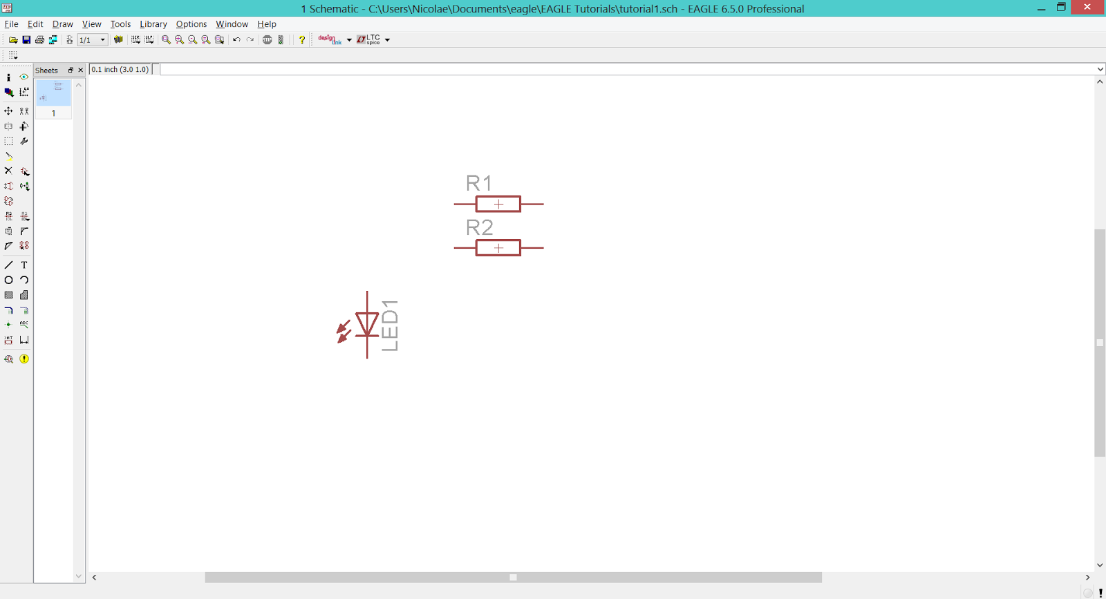
Return to the Add window and follow the next path: rcl.lbr > R-EU_ > R-EU_R1206. This is the R1206 SMD resistor that we need. Place two of them on the workspace and return to the Add window.
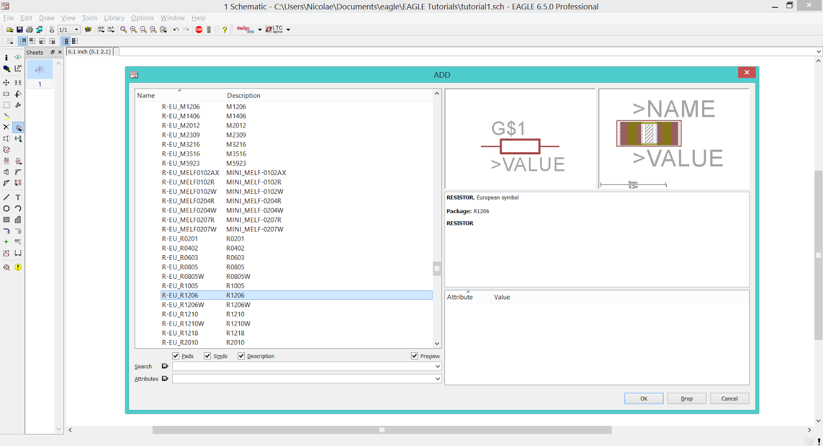
EAGLE CAD - RCL Library

EAGLE CAD - Placing The Resistors

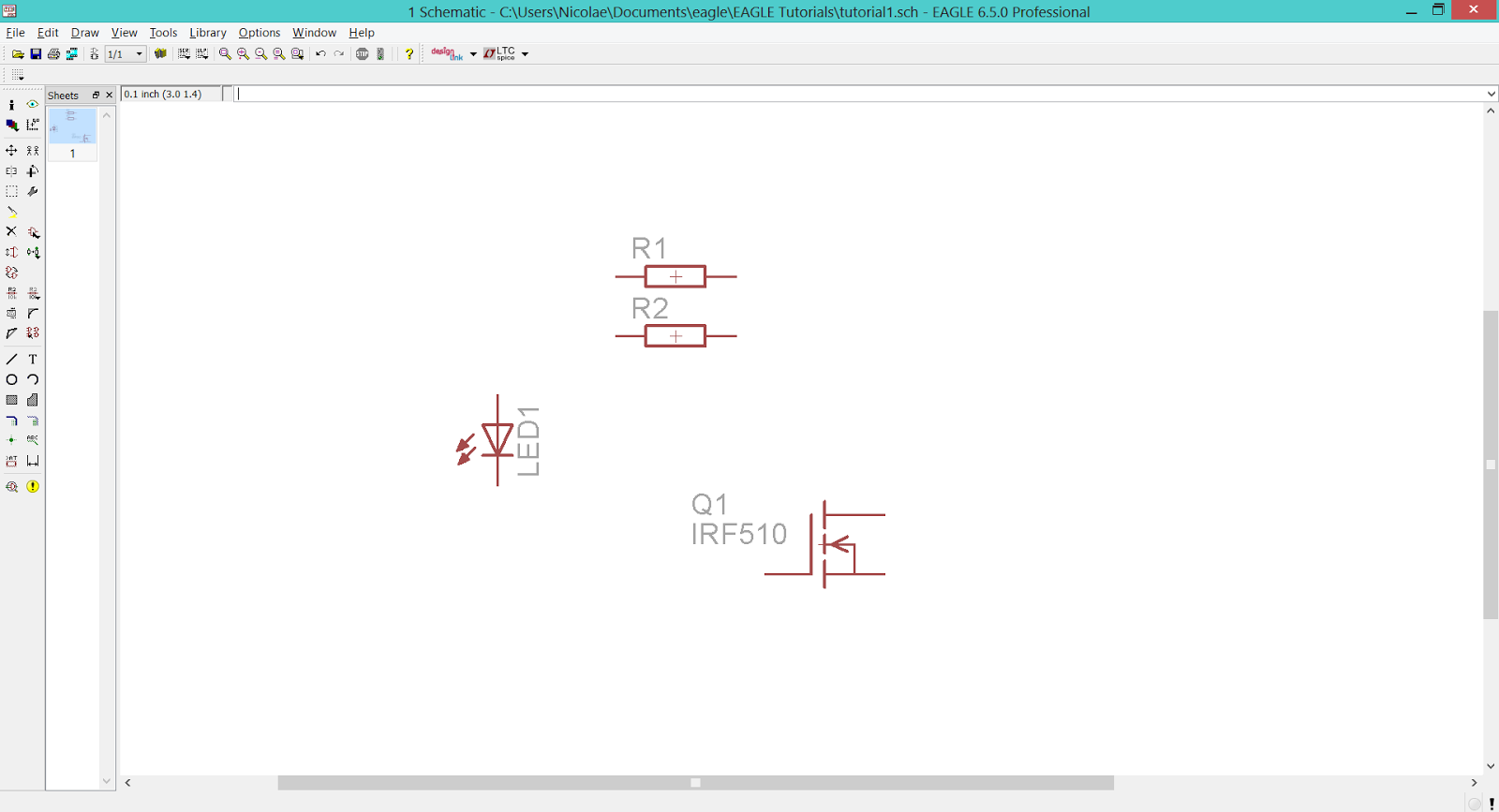
To add the N channel MOSFET go to transistor-fet.lbr > IRF510. Add one on the workspace.
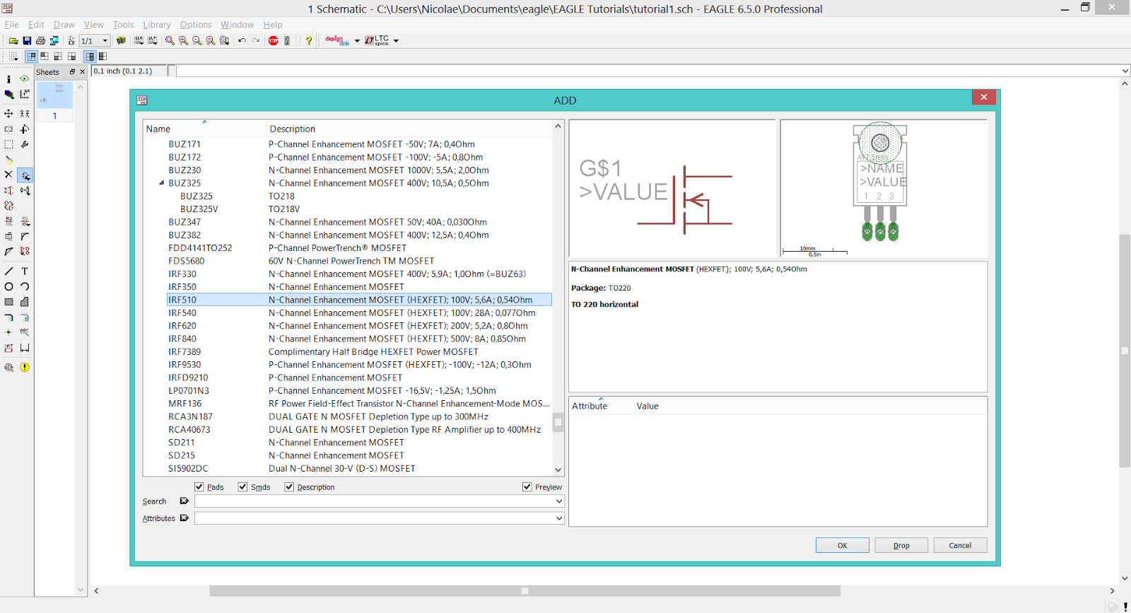
EAGLE CAD - Transistor-FET Library

EAGLE CAD - Placing The N-MOS Transistor

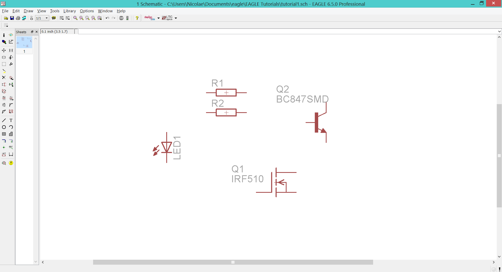
The NPN transistor is to be found in transistor-npn.lbr > BC847* > BC847SMD. Add one on the workspace.
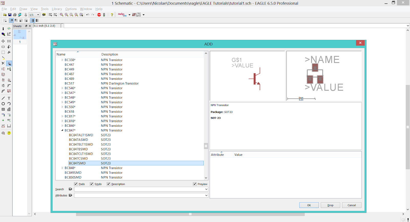
EAGLE CAD - Transistor-NPN Library

EAGLE CAD - Placing The NPN Transistor

Add the push-button from switch-omron.lbr > 10-XX.
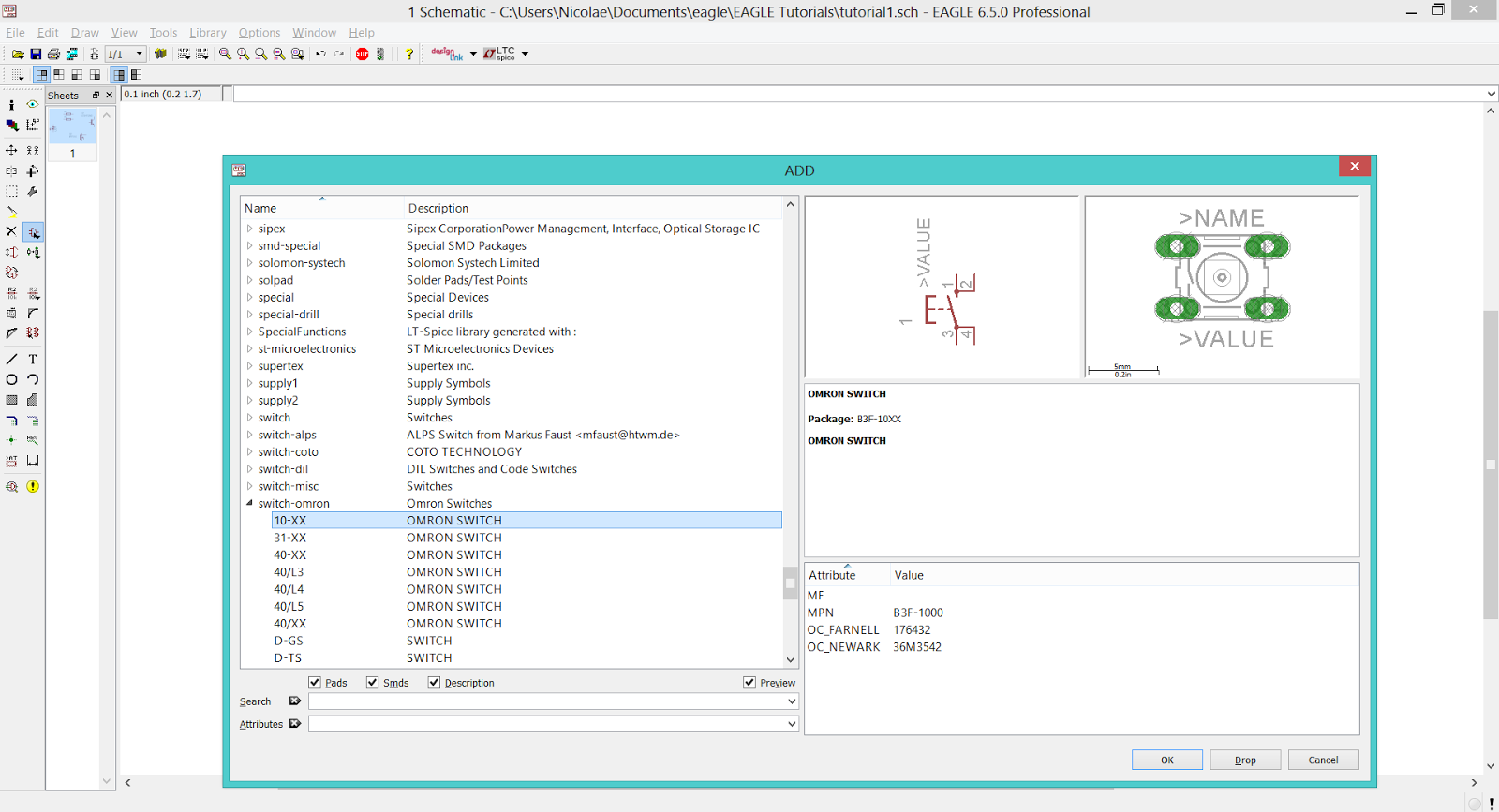
EAGLE CAD - Switch-Omron Library

EAGLE CAD - Placing The Push-Button

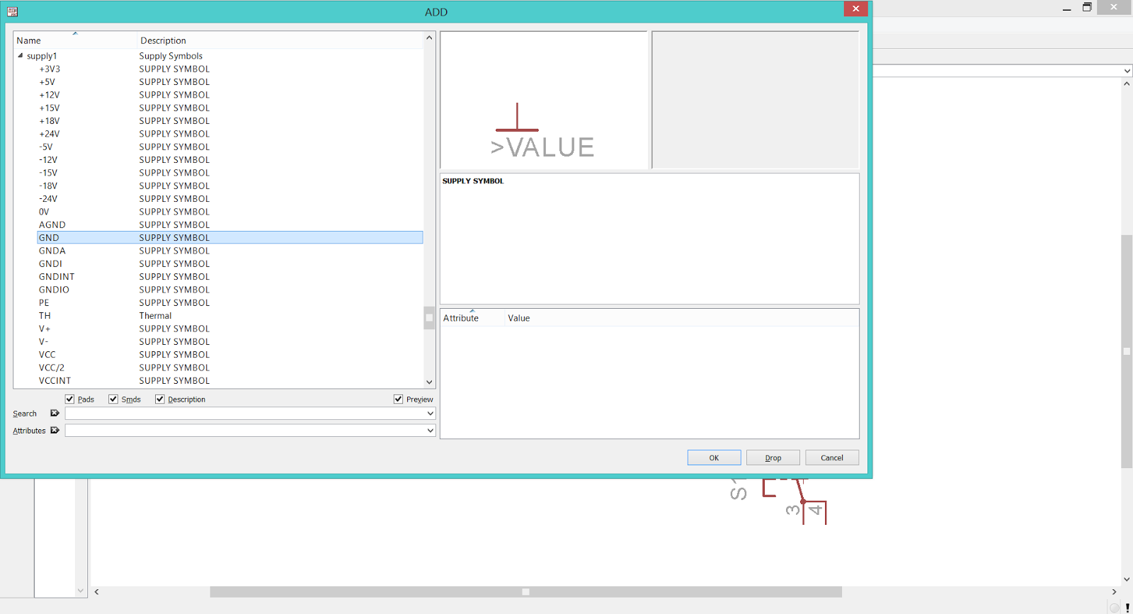
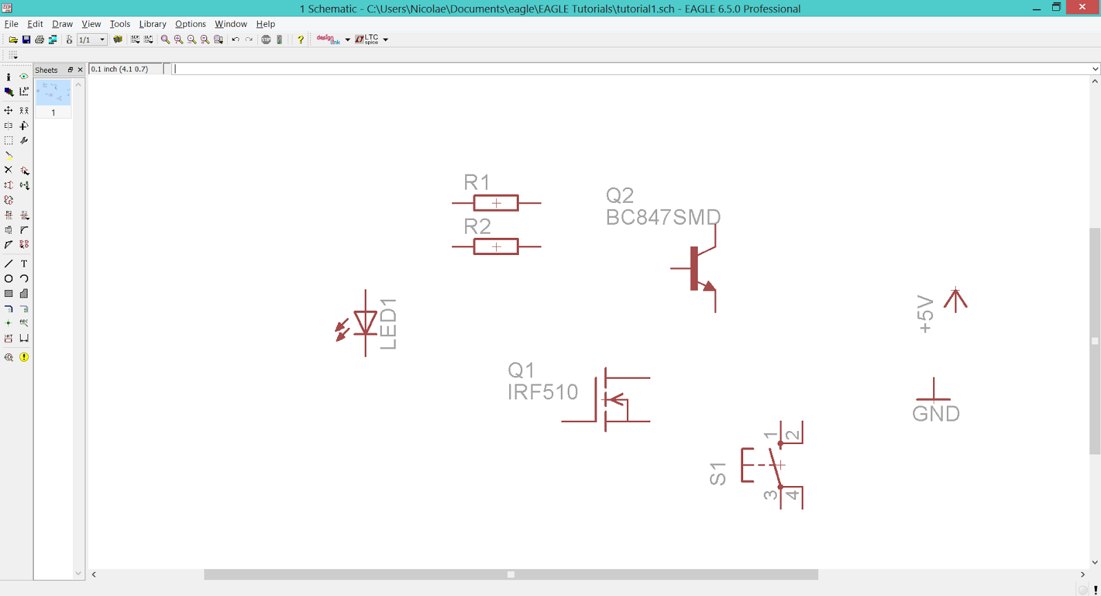
Finally, add the power rails from supply1.lbr > +5V and supply1.lbr > GND.
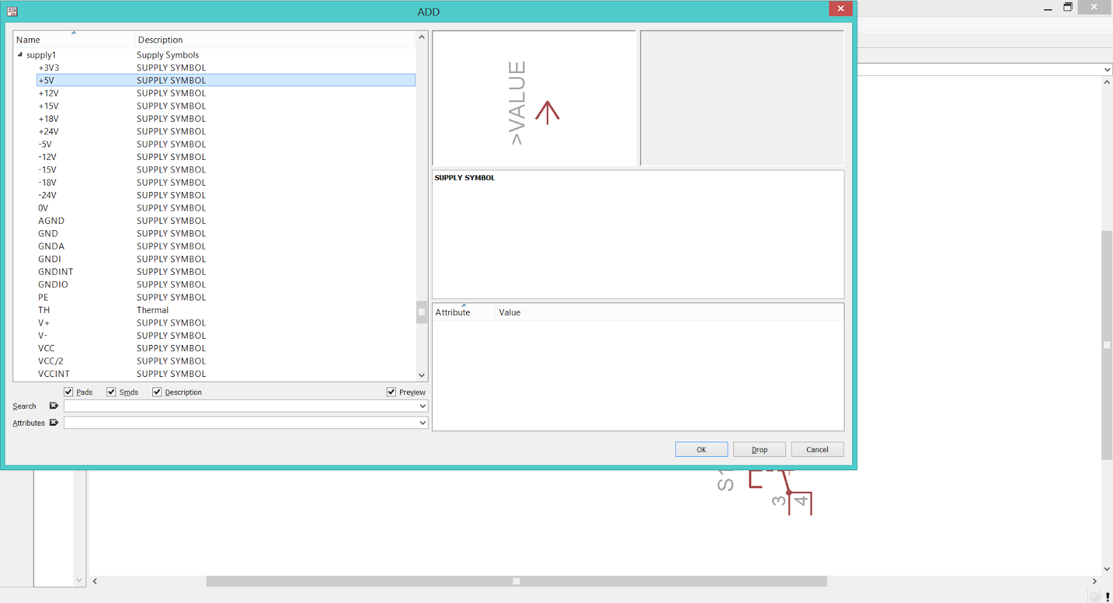
EAGLE CAD - Supply1 Library (+5V)

EAGLE CAD - Supply1 Library (GND)

EAGLE CAD - Placing The Power Symbols

Now we have all the needed components on the workspace, so we can put them in the right order and connect them with the Wire Tool.
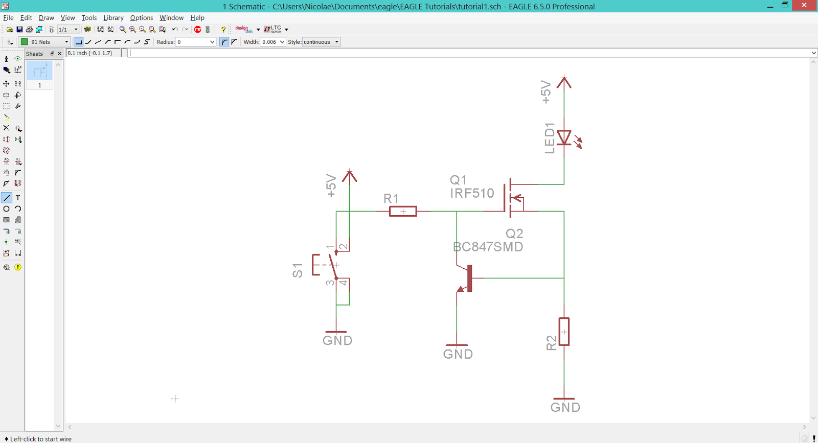
EAGLE CAD - Using The Wire Tool To Connect The Devices Together

Don't forget to place junctions (using Junction Tool) and give values to the devices (using Value Tool).
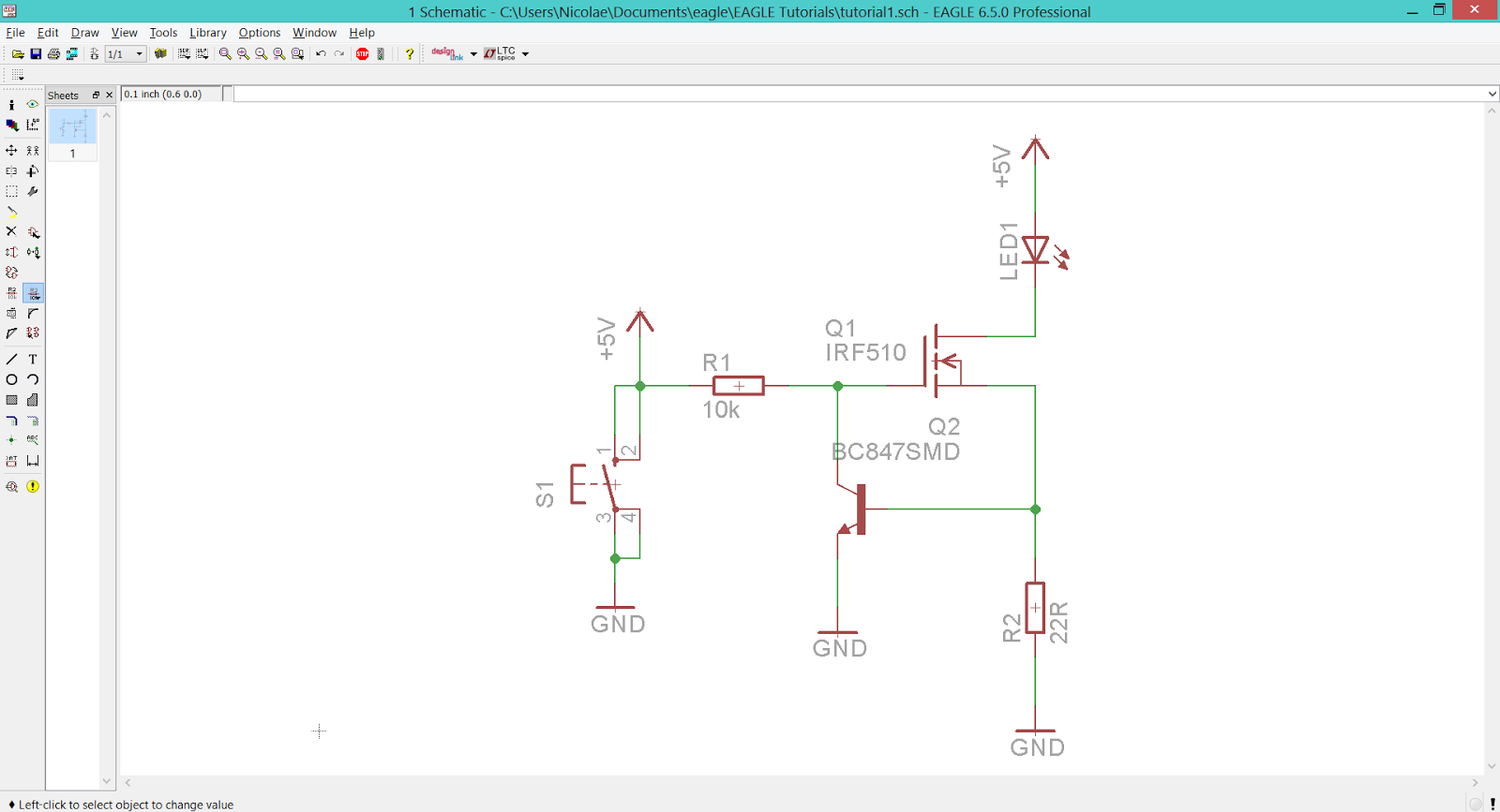
EAGLE CAD - Place Junctions And Give Values To The Devices

We're ready! The first schematic is up on her way to become a PCB. For a more 'easy to understand' version of this guide, check the following video (coming soon).